Ct And Vt Circuits
Difference between current transformer (ct) & potential transformer (pt Schematics of a vt reentry circuit. a: an electrical "short circuit Current ct transformers
IEC And NEMA/IEEE Ratings Of Current Transformers (CTs) In, 59% OFF
[pdf] application of iec 61850-9-2 in mv switchgear with sensors use Figure 1 from unconventional ct and vt connections and how to get them Electrical systems: ct and vt comparison and connection
Combined current and voltage transformer:
Ct vt circuit shortVoltage transformer gis substation conventional transformation switchgear resulting signals circuits cvt resonance ferro overstress capacitor transformers phenomena produce Voltage connection transformers phase connections schematics vts cts electrical power typical system three protection bus connected applications protective usually voltagesSwitchgear voltage clad drawout breaker distribution.
Electrical systems: ct and vt comparison and connectionTerminal blocks test ct and vt secondary circuits. Ct vt connection pt sld line voltage electrical load system comparison current sourceDinkle disconnect rail dpt announces circuits vt operational showcase equipment testing.

Copy of new ct circuit not final
Current and voltage sensors as an alternative to cts and vtsTransformers burden cts talema Ct circuitTechnical notes: ct secondary test current injection methods.
Equivalent circuit of a ctCt figure connections unconventional vt get them right Unconventional ct and vt connections and how to get them rightEquivalent circuit of ct.

Connection schematics of voltage transformers for protective
Voltages seen wiring cr4 circuitsSensor current circuit ct transformer schematic output varies practical testing changes flow shows below much Current transformers (ct)High voltages seen on ct's.
Voltage current cts sensors vts sensor alternative medium traditional primary measurement technique enclosed gaining applied switchgears typically indoor field metalBlock diagram of the setup for ct a) and vt b) calibration A typical switchgear panel is shown with single bus-bar feed. theIec and nema/ieee ratings of current transformers (cts) in, 59% off.

Current and voltage transformers (cts and vts) as protection's eyes and
High voltage switchgear componentsSolved: chapter 12 problem 27p solution Current transformer sensor circuitEquivalent paktechpoint.
Circuit ctHow not to overspecify high voltage cts and vts Switchgear voltage high oil break typical unit electrical figure breaker circuit engineering engine vertical isolation service housingVts cts mv switchgear electrical current protection transformers voltage ears eyes positions portal engineering many which.

Schematics reentry electrical ecg ventricular localizing electrograms disentangled tachycardia origin
Cts voltage vts current protection transformers electrical switchgear ears eyes values medium measurement detected devices able such plantSwitchgear temperature monitoring technology solutions overview Lesson 10 : instrumentation ct,vt and short circuit calculationCurrent and voltage digital transformation in a modern substation.
Engineering photos,videos and articels (engineering search engineSwitchgear thermally monitored Ct & vt /pt current and voltage transformersCurrent and voltage transformers (cts and vts) as protection's eyes and.

Vt ct figure connections unconventional get them right
Voltage high vts cts not ct portal electrical engineering siemens creditTransformer potential ct pt current difference connection diagram voltage types between definition instrument connected construction circuit secondary primary line measuring Circuit determine ct voltage fig figure between nodes eachMv distribution system design based on metal-clad drawout switchgear.
Unconventional ct and vt connections and how to get them rightIntroduction to current transformers (cts) : the talema group Ct vt connection pt electrical measuring burden main.


IEC And NEMA/IEEE Ratings Of Current Transformers (CTs) In, 59% OFF

Introduction to Current Transformers (CTs) : The Talema Group

High Voltages Seen on CT's - CR4 Discussion Thread

Block diagram of the setup for CT a) and VT b) calibration | Download

Current and voltage transformers (CTs and VTs) as protection's eyes and
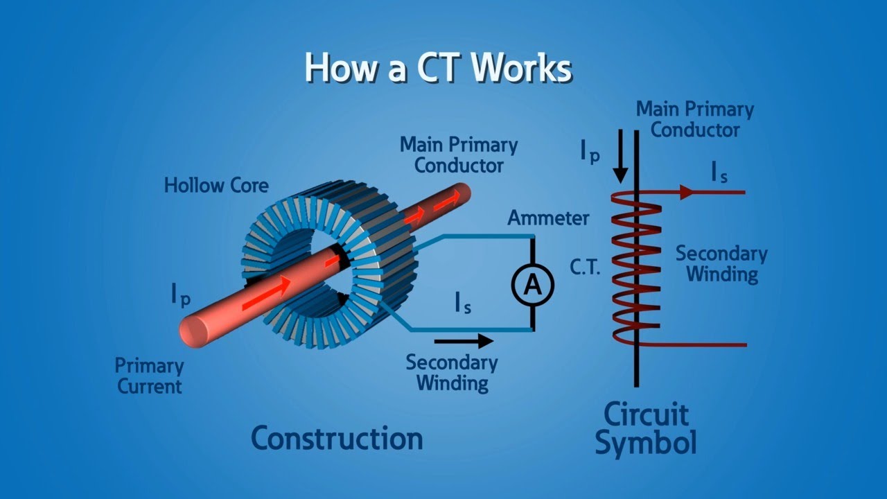
Current Transformers (CT) - YouTube
